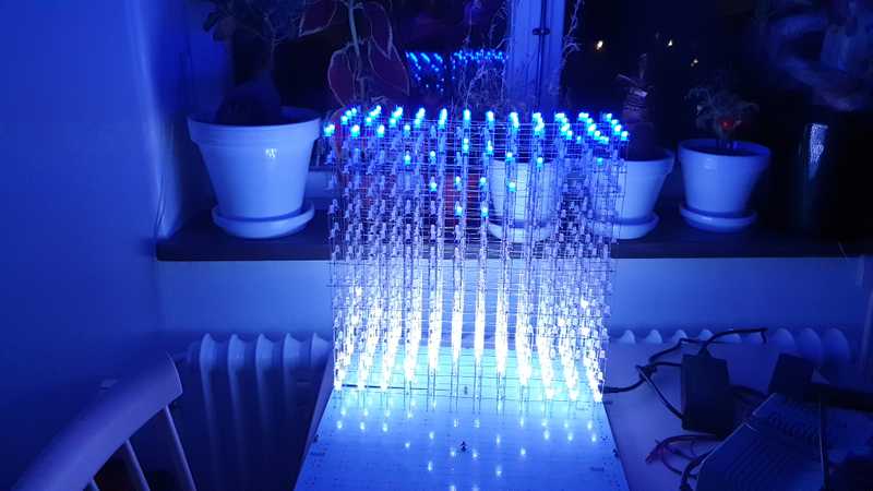
I’ve started working on a music visualizer using only hardware/microcontrollers. To start with, I want to have something cool to use as a 3D display. I found the awesome AuraCube 12x12x12 kit online, so I thought I might as well make this quite detailed tutorial for how to assemble it.
Note: This project requires a lot of soldering. I’m estimating you will go through an entire 200g solder spool and around 60hr of just soldering. You should invest in good lead-free solder with flux and a soldering station with controllable temperature (I recommend 310°C for this project).
Material
If you want to follow along, either buy an AuraCube 12x12x12 kit (search Ebay or the original author’s website).
Otherwise, I guess you can follow along using these materials:
- 1850 common anode RGB LEDs
- 750 lengths of 380mm tinned copper wire
- Wooden/3D-printed rig to solder the LEDs correctly. This is a must have, otherwise you will go insane!!
-
If you order the kit, you will get PCBs pre-populated with:
- 36 SM16126D LED driver ICs
- Whatever you prefer to drive the LED drivers (a combination of logic gates and shift registers, most likely)
- An MCU to control everything; the kit includes a STM32-based controller board that I intend to reprogram/replace eventually.
- Power supply; the LEDs themselves draw about 5A at 12V, I believe.
Step 1: Build a single 12 row of LEDs
You will have to repeat this step 12 times per layer.
Step 1.1: put LEDs into one of the row rigs
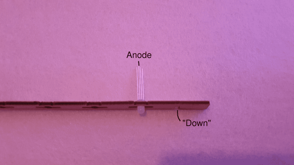
You need to make sure to keep track of a lot of leads, so make sure that you keep things in a proper orientation at all times. I opted to put the wooden rig strips with their stacking notch facing down, which has some advantages as you will see later.
Each RGB will have one common anode, and the three other leads control the R/G/B color intensity. I opted to work right-to-left, and always kept the anode to be in the second-to-left position at all times.
Be extremely careful to not break the brittle wood. If you do that by accident, I have had success with repairing them with Loctite superglue, but it’s probably not the best solution since Loctite has a tendency to melt when you solder next to it.
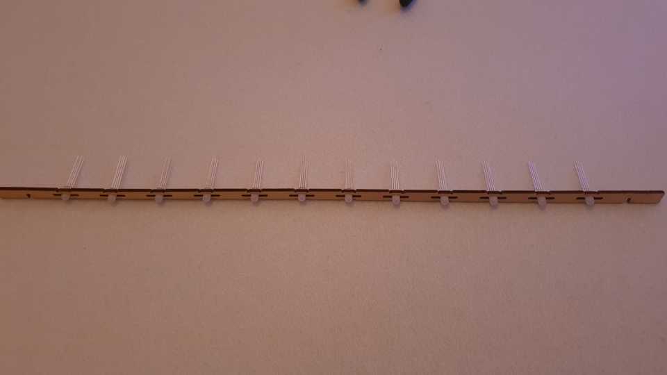
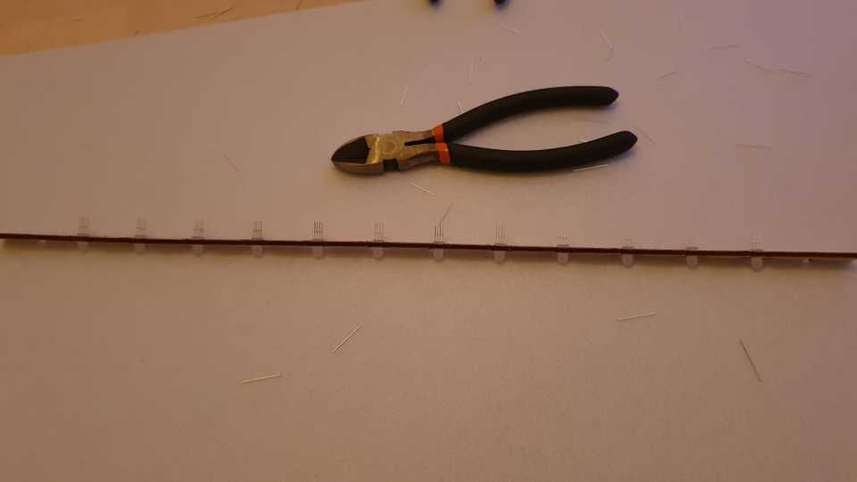
After all of the LEDs have been attached, a full row will look like this:
Step 1.2: Cut the LED leads to length
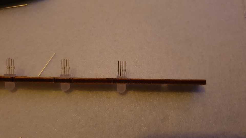
Each LED lead has a little “bump” where I guess it would normally be bent in a through-hole PCB. I have found that by cutting the LED leads at double that distance (or a bit more), you get the right amount of lead length to be able to do everything you need.
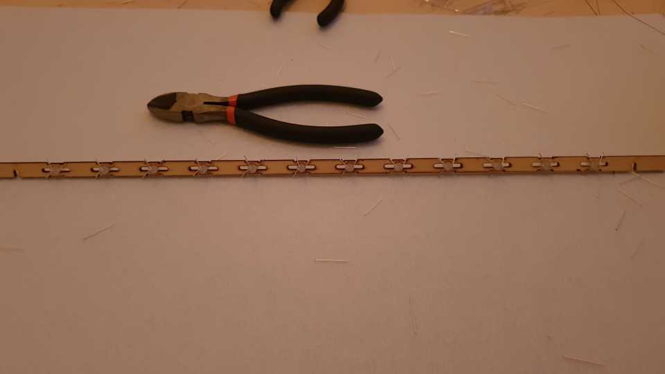
It’s best to cut all LEDs in a row at once. Sometimes, some of the LEDs will fall out and it might be hard to know which way it should go in again. To aid with that, each LED has a small notch on the side closest to the anode, so you want the notches on all of the LEDs to face left in the picture below. When you’re done, it should look like this:
Step 1.3: Folding the LED leads
You need to fold the LED leads so that they can connect to the tinned copper wires that will go vertically later on. To do that, you want the leads facing you, and work bottom-to-top (you hold the rig vertically towards you).
Starting from the lower-most LED, bend the first lead to the right, the second to the left, leave the third (which is the common anode) and bend the fourth left. You want the lead to pass the small groove in the wood, but still stick out over the edge of the wood, for things to work smoothly later.
Now you can repeat these steps 12 times to get 12 rows that go into a layer. In the next part, we will assemble the rows into a layer by soldering them into a frame.
