Some new parts arrived today (specifically 10kΩ resistors), and it’s time to connect the relay module with the controller circuit!
This is part 2 of this series; here is part 1, part 3, part 4, part 5.
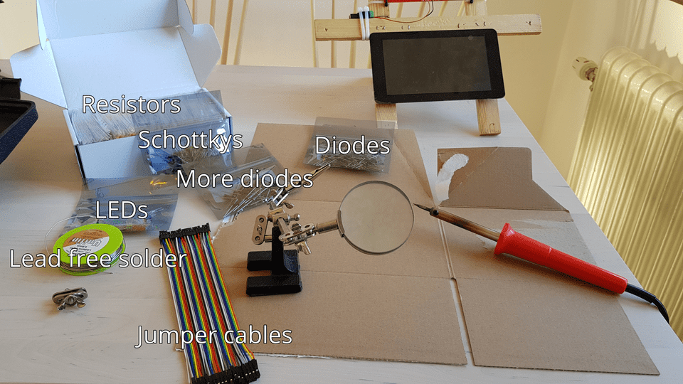
First, let’s get out some soldering equipment and circuitry. Here are some of the parts I intend to use for this project:
The goal for this time is to make the controller circuit able to toggle four of the eight relays on the relay module. The main difficulty when connecting everything up is that the relay module offers very little resistance when sending power through the control pins, so we need to add 10kΩ resistors as part of the circuit.
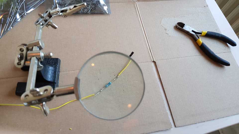
Since I didn’t want to use a breadboard for this project, I opted to just solder some resistors inline by splicing four jumper cables. It looks really dirty, but it works.
This is enough to hook up the relay board to the GPIO pins of the Raspberry Pi. I chose to use a completely separate circuit for the relay control pins and the relay coil circuit; the other option would be to share GND which poses some risk if there is a fluctuation in power supply for the relay coils.
I used GPIO pins 17, 18, 27 and 22 respectively for each relay, and the common GND on the Pi for the COM pin of the relay module.
Now we need a way to test whether everything works, which can be done with a simple GUI application.
I wrote a simple Qt application in Python to get started. I used the following libraries:
import collections
import sys

import RPi.GPIO as GPIO
from PyQt5.QtWidgets import QApplication, QMainWindow, QWidget, QHBoxLayout, QPushButton
First, we need a way to model a relay. Since we only need some very basic data, we can use a
namedtuple:
Relay = collections.namedtuple('Relay', ['gpio_pin', 'enabled'])Now we set up some general infrastructure for running a Qt application and using the GPIO library.
def main():
    try:
        # We want to use the hardware channel names
        GPIO.setmode(GPIO.BCM)

        # Matching the pin assignment I mentioned above
        relays = [
            Relay(17, False),
            Relay(18, False),
            Relay(27, False),
            Relay(22, False),
        ]

        # Configure our GPIO pins to be in output mode
        for relay in relays:
            GPIO.setup(relay.gpio_pin, GPIO.OUT)

        # Read the current state of the pins (in case some other app toggled them)
        for index, relay in enumerate(relays):
            relays[index] = relay._replace(enabled=GPIO.input(relay.gpio_pin))

        # Start a Qt app
        app = QApplication(sys.argv)

        # Create a MainWindow (to be defined below) that handles toggling the relays
        window = MainWindow(relays)
        window.showMaximized()

        # Run the native Qt main event loop
        ret = app.exec_()
    finally:
        GPIO.cleanup()

    sys.exit(ret)
For the GUI, the simplest layout I could come up with was to have one toggle button for each relay. We can create a simple window like so:
class MainWindow(QMainWindow):
    def __init__(self, relays):
        super(self.__class__, self).__init__()
        # The window owns keeping track of the current state of the relays
        self.relays = relays
        self.init_ui()

    def init_ui(self):
        self.setWindowTitle('Precip')
        main_widget = QWidget(self)

        # Arrange the buttons horizontally
        hbox = QHBoxLayout()

        # This hack is necessary to capture lambda variables correctly
        def create_handler(button, index):
            return lambda: self.toggle_relay(button, index)

        for index, relay in enumerate(self.relays):
            button = QPushButton('Relay ' + str(index + 1), main_widget)
            # Make the button state reflect the current state of the relay
            button.setCheckable(True)
            button.setChecked(relay.enabled)
            button.setStyleSheet('font-size: 36px; min-height: 48px')

            button.clicked.connect(create_handler(button, index))

            hbox.addWidget(button)

        main_widget.setLayout(hbox)

        self.setCentralWidget(main_widget)

    def toggle_relay(self, button, index):
        relay = self.relays[index]

        # Here's where we actually toggle the GPIO pin for the relay.
        # If this was non-prototype code, I would move this to a different class.
        if self.relays[index].enabled:
            GPIO.output(relay.gpio_pin, GPIO.LOW)
            enabled = False
        else:
            GPIO.output(relay.gpio_pin, GPIO.HIGH)
            enabled = True

        button.setChecked(enabled)
        self.relays[index] = relay._replace(enabled=enabled)
That’s it, we can make an application out of this!
if __name__ == '__main__':
    main()
Now, let’s run it. We need root access because we need to manipulate raw memory to access the GPIO state.
$ DISPLAY=:0 sudo -E python precip.pyIt actually works! The relays have LEDs indicating when they are toggled. What’s next is of course to actually have the relays power something (like water pumps or similar).

