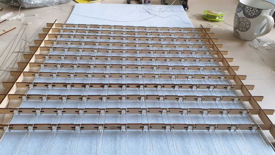
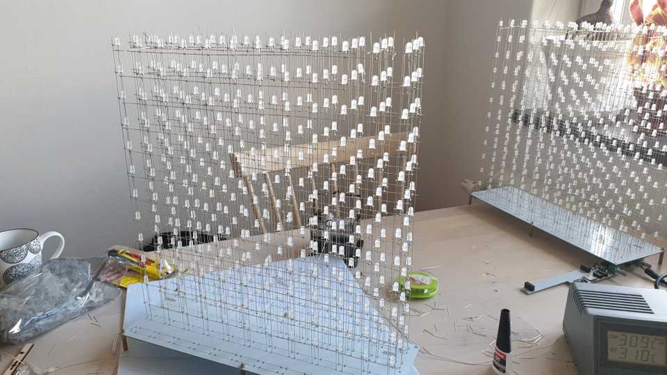
We are at a point where we hopefully know how to build all of the 12 layers of the cube.
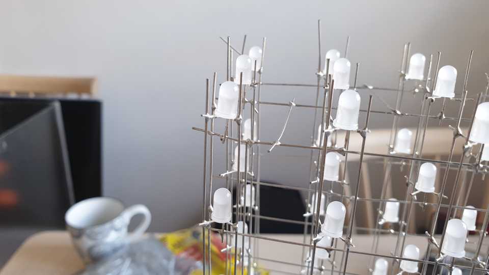
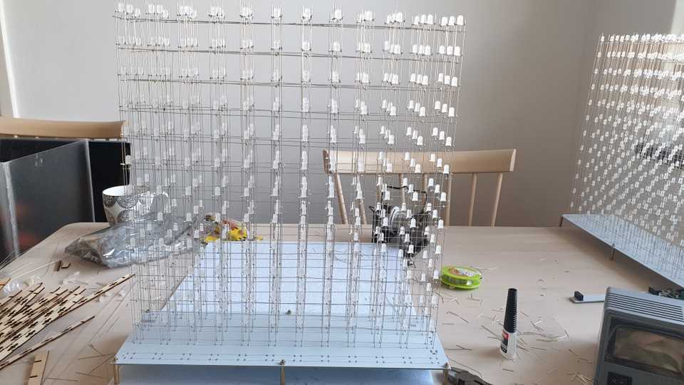
If you are not, you should follow Step 2 from the last part 12 times, and each time you have something like this, you are ready for step 3:
Step 3: Combine the layers
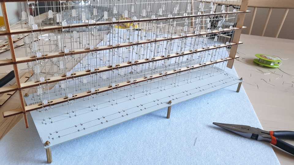
This is the point at which we will actually attach each layer to the bottom PCBs.
Step 3.1: Seat the layer
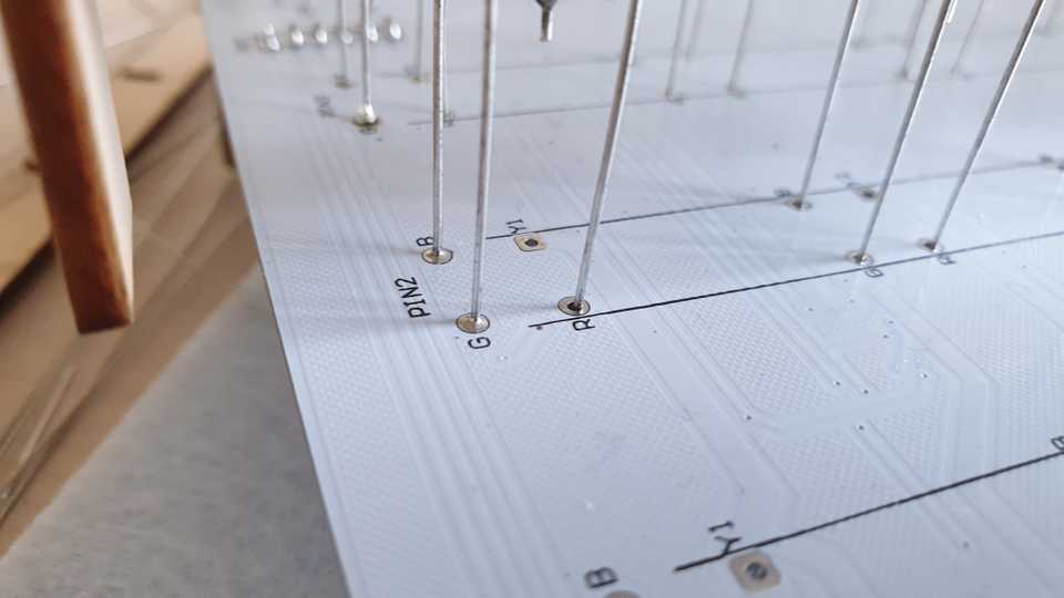
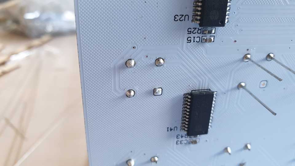
You need to thread through the wires from the layer into the R, G and B holes on the PCB. Make sure that you leave the Y (anode) hole open, otherwise it means that the layer is flipped the wrong way around!
What I usually do is to start from one side and use some tongs to thread through whatever wire that pokes against the PCB first. You need to make sure that the layer is at the right height. For the first layer, I used the wooden vertical support to determine the offset; after the first layer, you can usually eyeball it by comparing against previous layers.
Step 3.2: Secure the R/G/B wires
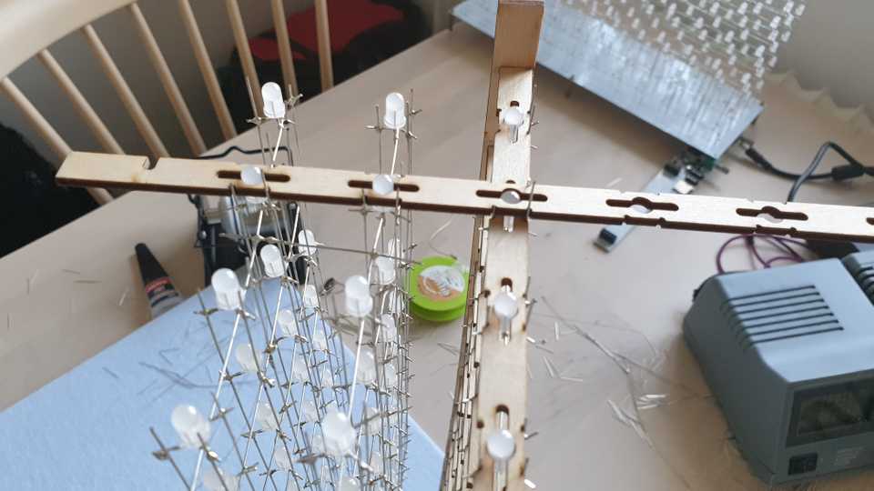
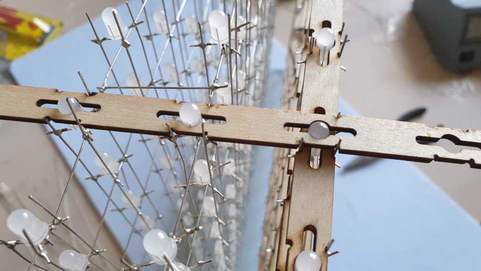
Now you need to make sure that the layer is properly aligned. For the first layer, you need to use something with a right angle and put it flat against the PCB, and hope that you get the alignment right. For the following layers, you can use one of the horizontal wooden spacers to determine the correct spacing:
For extra safety, you should do this on both sides of the layer:
Now you can solder just enough into a few of the holes in the PCB that the layer is fixed at the desired distance:
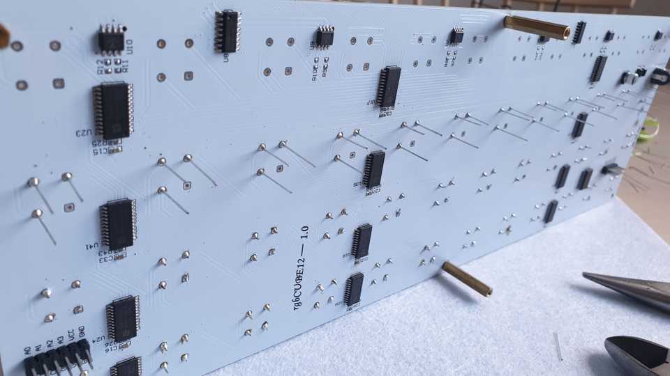
I prefer to solder the rest of the wires from the back side of the PCB.
It also makes sense to attach some spacers between each layer. It is safe to connect the anodes between two layers as long as they are from the same horizontal row.
Step 3.3: Wire up the anodes
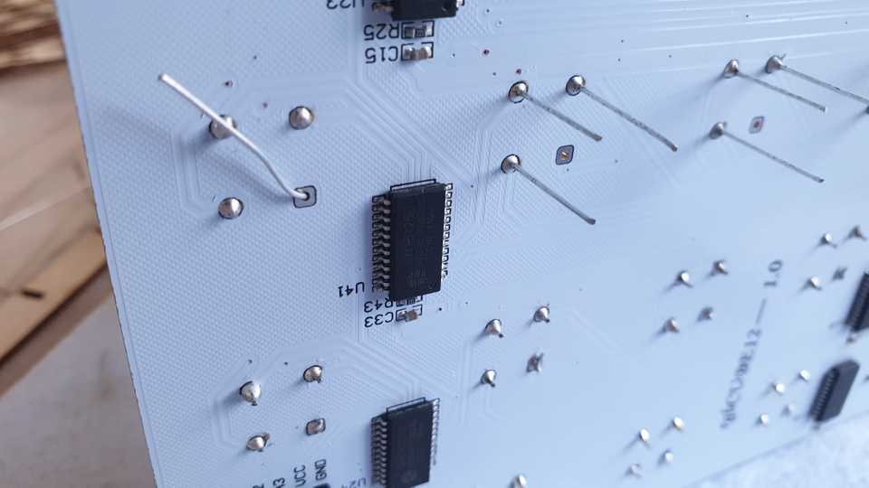
To complete our circuit, we need to connect all of the anode wires to the PCB as well. I guess you can make a choice about in which order the anodes will be wired up; this will determine how the final 3D animations will be “flipped” either upside-down or not. Whatever choice can easily be fixed in software later, I suppose, but I opted to connect the Y1 anode to the top layer which seems to make the LEDs update from top to bottom using the default firmwares people have floating around, so I guess that is how it is intended.
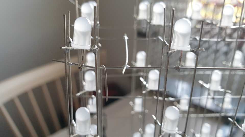
We start by “hooking” a wire up to the first layer anode:
Then, we thread the wire through the PCB and bend it a little bit to give it tension:
Finally, we can solder the top:
…and we can clean up the bottom:
When done, you get a nice anode “stairs” effect:
Step 3.4: Test
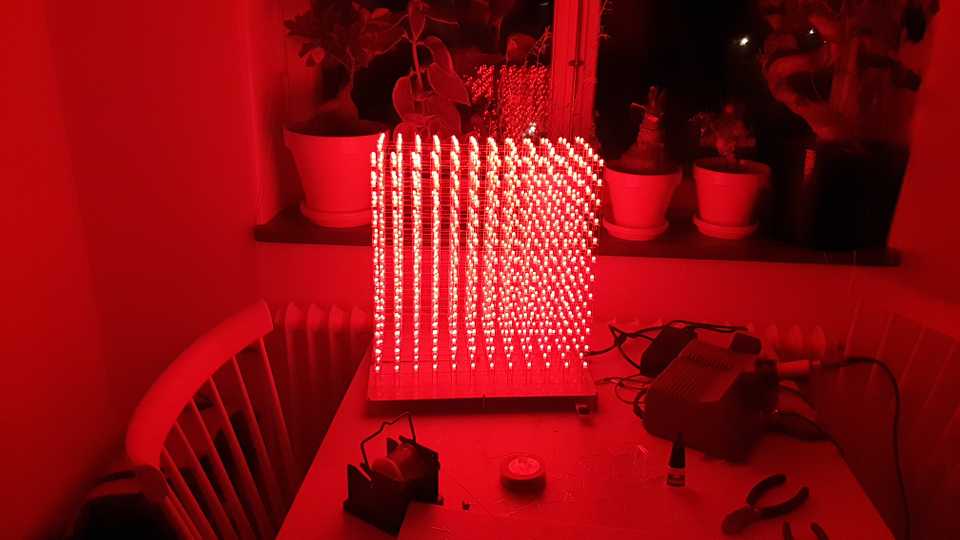
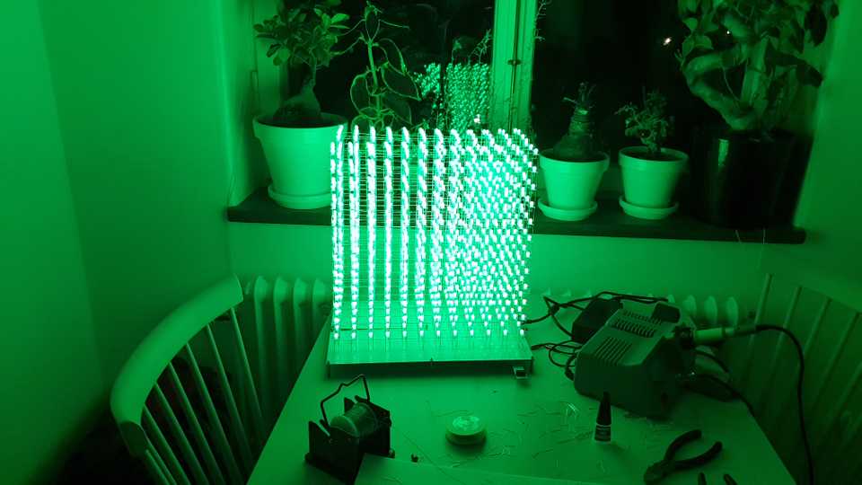
Now we can do a final test to ensure that all of the LEDs are working. I created a simple program to cycle through the primary colors: red, green, and blue.
After this, the cube hardware will be fully complete! Next, we will write some software and make the cube a bit nicer with a display case!
