Now we have a complete hardware platform and we can start writing some software! So far, I have only been using firmware written by others, but now it is finally time to create our own.
The code from this blog post is available here, although it will always be slightly ahead of the actual posts so that I can plan for the next steps :)
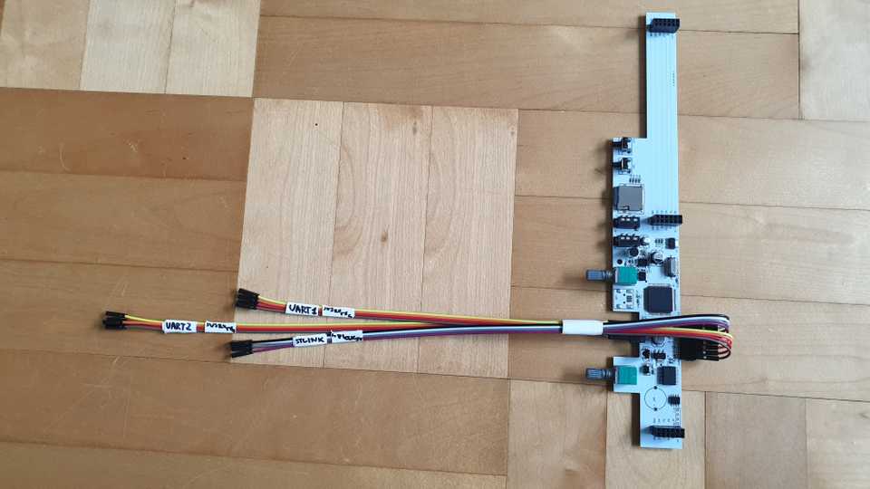
First, we need to be able to upload software to the cube. I de-soldered some of the pins on the controller board, added new pins at a 90° angle, and attached a few ribbon cables for the ST-LINK, UART1 and UART2 connectors. This is the result.
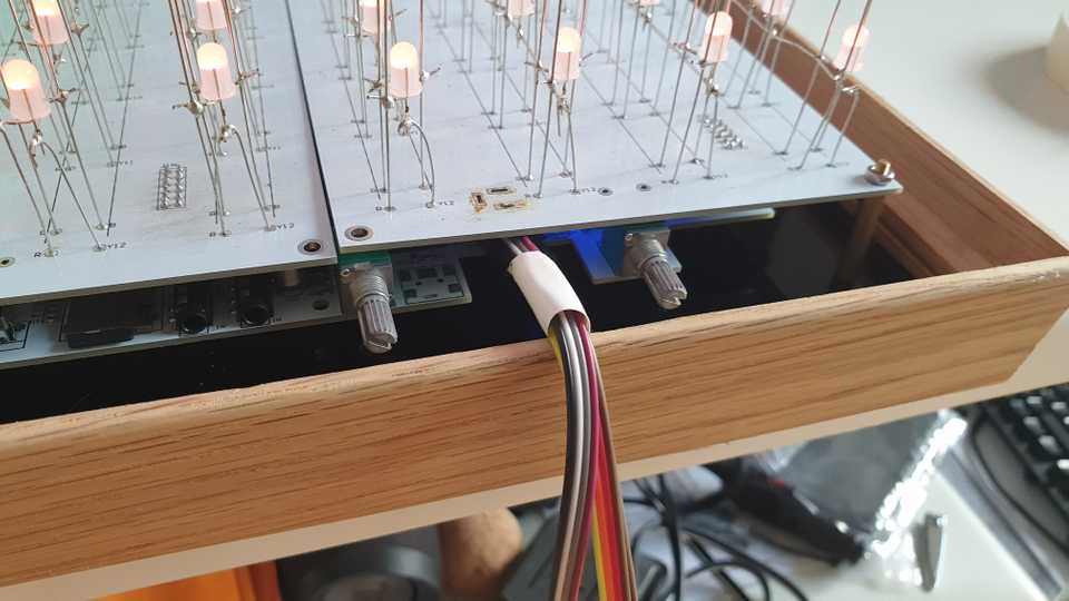
To now attach the board to the actual cube, we need to unfortunately desolder one of the power supply headers. The cube has 3 of them, so it shouldn’t be a big deal to just use a different one.
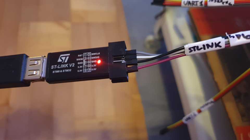
Finally, we can use the unfortunately proprietary ST-LINK V2 JTAG-to-USB adapter to connect to the board. Normally, I like to use a Black Magic Probe for development, but unfortunately the cube board isn’t supported (yet?).
Okay, so let’s write some code! First, you need to install Rust from https://rustup.rs/. Then, let’s use cargo (the
Rust build tool) to install cargo generate (which is similar to Python’s cookiecutter) and cargo add/rm/upgrade (for
easily dealing with dependencies).
$ cargo install cargo-generate cargo-editThen, we can add support for cross-compiling to Thumb ARM v7 HF (which is what the chip uses).
$ rustup target add thumbv7em-none-eabihfNow we will use cargo generate to generate a new project from a template, like so.
$ cargo generate \
  --git https://github.com/rust-embedded/cortex-m-quickstart \
  --name auracube
$ cd auracube
To target our device by default, we can set some configuration in the .cargo/config file:
[target.'cfg(all(target_arch = "arm", target_os = "none"))']
rustflags = [
  "-C", "link-arg=-Tlink.x",
]

[build]
# Cortex-M4F and Cortex-M7F (with FPU)
target = "thumbv7em-none-eabihf"
Let’s start by creating a simple LED display driver. It will consist of a matrix part (used to store the display
data) and a display part (used to actually display the contents onto the cube). We create a file called
src/led/matrix.rs and add some basic data structures.
use core::ops;

pub const CUBE_SIZE: usize = 12;

#[derive(Clone, Copy, Debug, Default, Eq, Ord, PartialEq, PartialOrd)]
pub struct LedMatrix {
    pub cells: [[[Color; CUBE_SIZE]; CUBE_SIZE]; CUBE_SIZE],
}

#[derive(Clone, Copy, Debug, Default, Eq, Ord, PartialEq, PartialOrd)]
pub struct Color {
    pub r: u8,
    pub g: u8,
    pub b: u8,
}

#[derive(Clone, Copy, Debug, Default, Eq, Ord, PartialEq, PartialOrd)]
pub struct Coord {
    pub x: usize,
    pub y: usize,
    pub z: usize,
}
Our cube has side length 12, and we will use a 3-dimensional array of colors to store all of the LED values. We will use a conventional RGB representation for the colors. Also, we can create a utility struct for describing coordinates within the cube.
I want to index the coordinate array as [z][y][x] and make the Z axiz point up, and X and Y axes be horizontal. This
ensures that we can display the cube contents layer-by-layer from top to bottom and have pretty high data locality for
performance reasons. The cube probably doesn’t have any memory cache to speak of, but data locality still matters for
loop vectorization etc.
We can ensure that this convention is upheld by adding some utility functions, and overloading the index operator for the matrix itself.
impl LedMatrix {
    pub fn xyz(
        &self,
        x: usize,
        y: usize,
        z: usize,
    ) -> &Color {
        &self.cells[z][y][x]
    }

    pub fn xyz_mut(
        &mut self,
        x: usize,
        y: usize,
        z: usize,
     ) -> &mut Color {
        &mut self.cells[z][y][x]
    }
}

// For the `let color = matrix[Coord { x, y, z }]`
// pattern
impl ops::Index<Coord> for LedMatrix {
    type Output = Color;

    fn index(&self, index: Coord) -> &Self::Output {
        self.xyz(index.x, index.y, index.z)
    }
}

// For the `matrix[Coord { x, y, z }] = color`
// pattern
impl ops::IndexMut<Coord> for LedMatrix {
    fn index_mut(
        &mut self,
        index: Coord,
    ) -> &mut Self::Output {
        self.xyz_mut(index.x, index.y, index.z)
    }
}
Okay, now for the display driver. The way the cube is constructed, there are 4 bus select pins that select a particular layer of the cube (horizontal plane); in our case that will correspond to a certain Z coordinate. There are some multiplexer chips that then connect the right anode for that layer to ground (the vertical wires that we soldered in a previous post).
Then, once a layer has been selected, there is one shift register/LED driver per cube PCB (remember that there are 3) and each PCB contains 4 vertical slices of LEDs. I’m not sure, but it would seem like the shift registers store a total of; 192 bits per PCB; there are first 12 unused bits, then 1 bit for green, 1 bit for red and 1 bit for blue for the first LED, 1G1R1B for the second LED and so on until the end of a row; then follows 12 unused bits, 1G1R1B for each LED in the second row, and so on.
Shift register A:
Y  0: XXXXXXXXXXXXGRBGRBGRBGRBGRBGRBGRBGRBGRBGRBGRBGRB
Y  1: XXXXXXXXXXXXGRBGRBGRBGRBGRBGRBGRBGRBGRBGRBGRBGRB
Y  2: XXXXXXXXXXXXGRBGRBGRBGRBGRBGRBGRBGRBGRBGRBGRBGRB
Y  3: XXXXXXXXXXXXGRBGRBGRBGRBGRBGRBGRBGRBGRBGRBGRBGRB
               X: 0  1  2  3  4  5  6  7  8  9  10 11

Shift register B:
Y  4: XXXXXXXXXXXXGRBGRBGRBGRBGRBGRBGRBGRBGRBGRBGRBGRB
Y  5: XXXXXXXXXXXXGRBGRBGRBGRBGRBGRBGRBGRBGRBGRBGRBGRB
Y  6: XXXXXXXXXXXXGRBGRBGRBGRBGRBGRBGRBGRBGRBGRBGRBGRB
Y  7: XXXXXXXXXXXXGRBGRBGRBGRBGRBGRBGRBGRBGRBGRBGRBGRB
               X: 0  1  2  3  4  5  6  7  8  9  10 11

Shift register C:
Y  8: XXXXXXXXXXXXGRBGRBGRBGRBGRBGRBGRBGRBGRBGRBGRBGRB
Y  9: XXXXXXXXXXXXGRBGRBGRBGRBGRBGRBGRBGRBGRBGRBGRBGRB
Y 10: XXXXXXXXXXXXGRBGRBGRBGRBGRBGRBGRBGRBGRBGRBGRBGRB
Y 11: XXXXXXXXXXXXGRBGRBGRBGRBGRBGRBGRBGRBGRBGRBGRBGRB
               X: 0  1  2  3  4  5  6  7  8  9  10 11
This means that we can only turn on one Z-layer of the cube at any time, and each LED can only be turned on 100% or off 0%. To display a 3D image, we need to cycle through the cube Z-wise extremely quickly, and then flash all of the LEDs on or off the appropriate amount of time to create the right colors.
Let’s start creating a driver for this in src/led/driver.rs. First, we create a structure to store which Z layer we
are currently on, and a bit field which I will explain later. Then, we also need two things that do the actual IO for
us: a layer selector and something that pushes data into the shift registers. We can leave them abstract as traits
for now.
#[derive(Debug)]
pub struct LedDisplay<E, L, D>
where
    L: LayerSelector<Error = E>,
    D: DataBus<Error = E>,
{
    layer_selector: L,
    data_bus: D,
    z: usize,
    bit: u8,
}

pub trait LayerSelector {
    type Error;

    /// Configures the pin multiplexers to select a
    /// certain Z layer.
    fn select_layer(
        &mut self,
        layer: usize
    ) -> Result<(), Self::Error>;
}

pub trait DataBus {
    type Error;

    /// Set when we want to configure the shift
    /// registers; otherwise random writes to the
    /// pins might cause the registers to change for
    /// random reasons.
    fn set_stk(
        &mut self,
        stk: bool
    ) -> Result<(), Self::Error>;

    /// Set whether the output of the shift registers
    /// should be shown on the actual LED matrix; this
    /// should be set to false while we update the
    /// LEDs.
    fn set_oe(
        &mut self,
        stk: bool
    ) -> Result<(), Self::Error>;

    /// Send bits of data in parallel to the A, B and C
    /// shift registers.  They share the same clock and
    /// hence need to be updated at the same time.
    fn send_data(
        &mut self,
        data_a: bool,
        data_b: bool,
        data_c: bool
    ) -> Result<(), Self::Error>;
}
Now, the idea is that we will display all of the colors of the matrix bit-by-bit. We will start with the least significant bit (LSB) of all colors, and if that bit is set we turn on the relevant LED for a super short time. We do this for all of the Z layers. Then, we continue with the next bit, and leave the LEDs turned on for a slightly longer time. This repeats 8 times for all of the bits. The last bit (the MSB) will be left showing the longest, since it contributes the most to the value of the color.
Let’s do the math of how long the LEDs should be turned on. Let’s first decide on a total refresh rate:
// How many times per second should the cube refresh
// completely
const UPDATE_RATE_HZ: f32 = 60.0;
Now, the naive approach would be to cycle through all the Z layers 12 times as fast (so 60 * 12 Hz) and then for each
bit spend a proportional amount of time; so the MSB would be updated at 60 * 12 * 2^0 Hz, the next most significant at
60 * 12 * 2^1 Hz, then at 60 * 12 * 2^2 Hz, up to the LSB at 60 * 12 * 2^7 Hz.
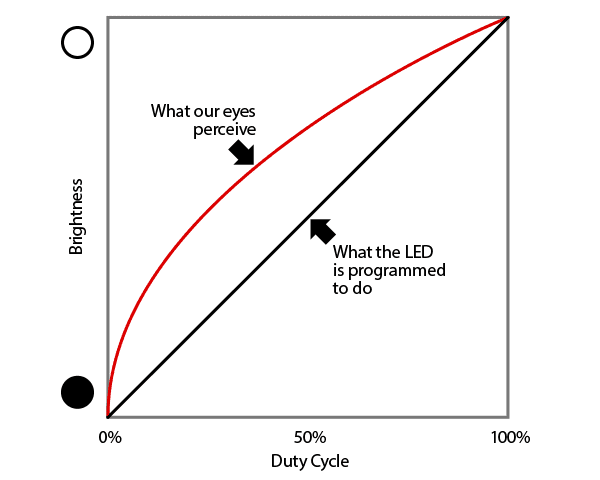
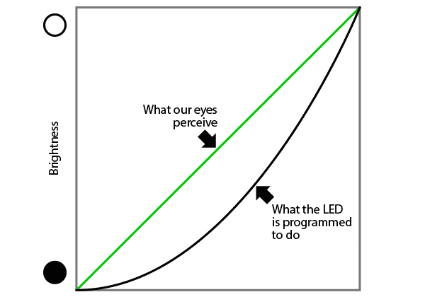
However, the human eye does not perceive light linearly, which is what we would get with those 2^0..2^7 weights. We
need to do something which is called gamma correction.
Quoting that link, if we do linear light intensity, the color gradient will be perceived as too aggressive:
By compensating for this, we can get a more linear perceived color gradient:
Computing a gamma curve should be pretty straight-forward, as it is just the exponential function with a fixed exponent.
Usually, 2.3 is a good starting point for a gamma coefficient. First, let’s write a meta-program in Python that will
generate a gamma curve as Rust code.
import math
import subprocess


def gamma(num_steps, gamma):
    gammas = [math.pow(x, gamma) for x in range(num_steps)]
    return [x / max(gammas) for x in gammas]


def rescale_all(min_value, max_value, gammas):
    return [max(min_value, min(max_value, round(x * (max_value - min_value + 1)))) for x in gammas]


def main():
    gamma_coefficient = 2.3
    steps = 8
    gamma_values = rescale_all(1, 255, gamma(steps, gamma_coefficient))

    with open("src/led/gamma.rs", "w") as output:
        output.write("//! An auto-generated {}-step brightness table: gamma = {}\n\n".format(steps, gamma_coefficient))
        output.write("pub const GAMMA_TABLE: &[u8; {}] = &[\n".format(steps))
        for value in gamma_values:
            output.write("\t %d,\n" % value)
        output.write("];\n\n")
        output.write("pub const GAMMA_SUM_WEIGHT: f32 = {};\n".format(float(sum(gamma_values))))

    subprocess.check_call(["cargo", "fmt"])


if __name__ == "__main__":
    main()
This gives us this gamma table that we can use in src/led/gamma.rs:
//! An auto-generated 8-step brightness table:
//! gamma = 2.3

pub const GAMMA_TABLE: &[u8; 8] = &[
    1, 3, 14, 36, 70, 118, 179, 255
];

pub const GAMMA_SUM_WEIGHT: f32 = 676.0;
First of all, we can now determine a base frequency that we need to use when updating the cube; since we will turn on each LED for the duration of each value in the gamma table, the base frequency needs to be multiplied by the sum of the gamma table. However I realize the math is a bit handwavy here, I’ll probably revisit this at some point.
const BIT_DEPTH: f32 = 8.0;
const ADJUSTED_UPDATE_RATE_HZ: f32 =
    gamma::GAMMA_SUM_WEIGHT * UPDATE_RATE_HZ *
    BIT_DEPTH * matrix::CUBE_SIZE as f32;
Now, let’s use this to update the cube. First, we can make a constructor for our driver:
impl<E, L, D> LedDisplay<E, L, D>
where
    L: LayerSelector<Error = E>,
    D: DataBus<Error = E>,
{
    pub fn new(layer_selector: L, data_bus: D) -> Self {
        let bit = 0;
        let z = 0;

        Self {
            layer_selector,
            data_bus,
            bit,
            z,
        }
    }
Now, let’s add an update function which gets a reference to the matrix to display, and keeps track of the state variables (currently displayed Z layer and color bit):
    #[inline]
    pub fn update(
        &mut self,
        matrix: &super::matrix::LedMatrix
    ) -> Result<Option<u32>, E> {
        self.z += 1;
        self.z %= matrix::CUBE_SIZE;

        let next_freq = if self.z == 0 {
            self.bit += 1;
            self.bit %= 8;

            let b = self.bit as usize;
            let new_freq_hz =
                ADJUSTED_UPDATE_RATE_HZ /
                gamma::GAMMA_TABLE[b] as f32;
            Some(new_freq_hz as u32)
        } else {
            None
        };

        // To ensure the cube updates top-down
        let flipped_z = matrix::CUBE_SIZE - self.z - 1;
        self.update_z_bit(flipped_z, self.bit, matrix)?;
        Ok(next_freq)
    }
The idea is that this function returns Some(frequency) when the update frequency needs to change, and None
otherwise.
Finally, we need the update_z_bit method (not a super great name) that actually writes out the color data:
    #[inline]
    fn update_z_bit(
        &mut self,
        z: usize,
        bit: u8,
        matrix: &super::matrix::LedMatrix,
    ) -> Result<(), E> {
        self.data_bus.set_oe(false)?;
        self.layer_selector.select_layer(z)?;

        self.data_bus.set_stk(false)?;

        for y_slice in 0..matrix::CUBE_SIZE / 3 {
            for _ in 0..matrix::CUBE_SIZE {
                self.data_bus.send_data(
                    false,
                    false,
                    false
                )?;
            }
            for x in 0..matrix::CUBE_SIZE {
                let color_a =
                    matrix.xyz(x, 0 + y_slice, z);
                let color_b =
                    matrix.xyz(x, 4 + y_slice, z);
                let color_c =
                    matrix.xyz(x, 8 + y_slice, z);

                self.data_bus.send_data(
                    color_a.g & (1u8 << bit) != 0,
                    color_b.g & (1u8 << bit) != 0,
                    color_c.g & (1u8 << bit) != 0,
                )?;
                self.data_bus.send_data(
                    color_a.b & (1u8 << bit) != 0,
                    color_b.b & (1u8 << bit) != 0,
                    color_c.b & (1u8 << bit) != 0,
                )?;
                self.data_bus.send_data(
                    color_a.r & (1u8 << bit) != 0,
                    color_b.r & (1u8 << bit) != 0,
                    color_c.r & (1u8 << bit) != 0,
                )?;
            }
        }

        self.data_bus.set_stk(true)?;
        self.data_bus.set_oe(true)?;
        Ok(())
    }
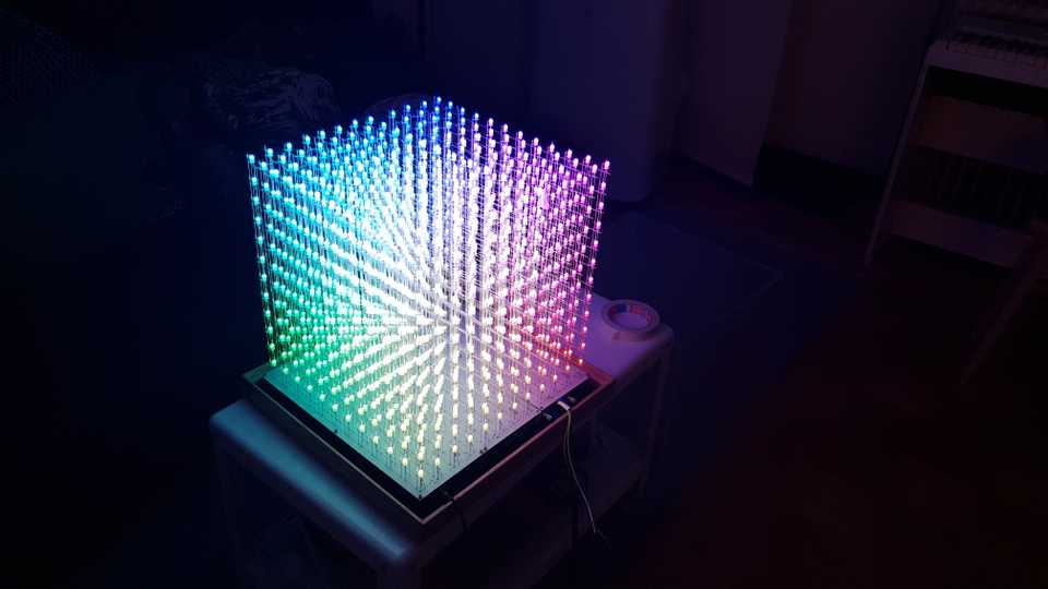
So far, we have written plain Rust code (and not imported a single library function!) so this code can really run anywhere. In the next part, we will talk about how to use the RTFM framework to actually communicate with the hardware and hook this all up. However, to show that our gamma calculations had the desired effect, here is already a preview image showing some color gradients.
