As someone who suffers from having too many hobbies and too little time, it might sound silly to add another one to the mix. One of them being indoors vegetable cultivation already means that I have a big time sink that needs to be tended to regularly.
When somebody suggested I build an automated irrigation system, it struck me as something that would take way too much time from my already near-negative supply. The idea remained in the back of my mind for a while, though, and was way too alluring for it not to percolate into an almost fully baked idea for a project a little while later.
This is part 1 of this series; here is part 2, part 3, part 4, part 5.
Structure
The basic idea is very simple: There should be a water supply that I only have to re-fill very rarely, and a bunch of automatic pumps that use that supply to water plants at different intervals. The watering schedule is to be determined from the input of various sensors, for example thermometers or soil moisture sensors.
There should be some sort of monitoring software that builds a model around the correlation between pumping rates and sensor inputs, and uses that to feed the pumps, as well as to provide monitoring over the web for remote access.
I decided to have four individually addressable pump loops as a start, with the ability to add more as needed.
Parts
I decided to mostly use parts I already had laying around, which meant that the project would maybe not look the best but hopefully be functional.
As the base unit, I’m using a Raspberry Pi 3B+, which makes it easy to deal with the unit since I don’t need to route ethernet cables; there’s a built-in Wifi chip.
I’m combining that with a 7 inch touch screen display and associated controller. It’s way overkill for an irrigation system but I wanted some way to display information on the device itself.
Since I don’t have a 3D printer, I took an old apple cider crate and re-used the wooden scraps for a frame, and tied everything together with staples and cable ties. Yes, this is very much a prototype at this stage!
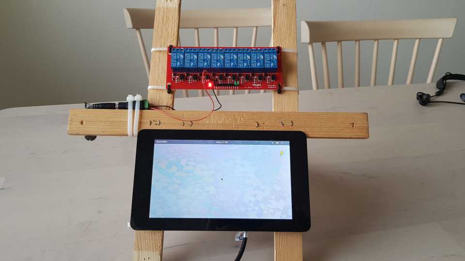
The basic unit looks like this:
For now it’s running GNOME 3 on Arch Linux ARM for ARMv7hf to get started; I needed an easy way to configure power management, network connectivity etc. without too much hassle. Eventually, I will probably replace it with something more light-weight.
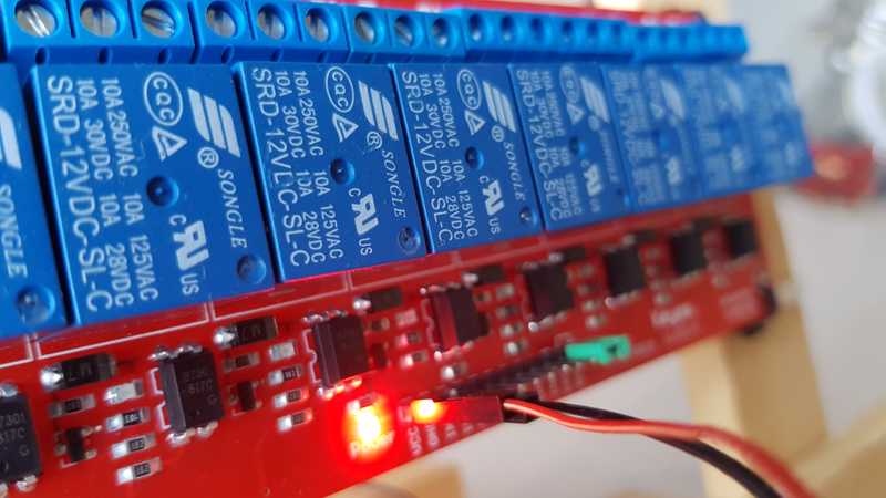
On top is the 8 channel 12V relay array. It forms a completely separate circuit; I haven’t connected the array to the main controller in any way yet.
The main unit is powered via a standard 5V 2.5A USB micro connector. The relay unit needs a higher voltage, so I gave it a dedicated 12V mains feed coming in from the left in the picture.
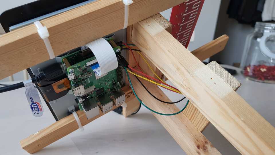
The LCD has its own controller board at the bottom which also takes care of power distribution. On top of that sits the Raspberry Pi itself, connected to the LCD with a ribbon cable and some jumper wires for power and optional control shenanigans.
Next steps
I’m out of 10kΩ resistors, as well as diodes, so I can’t actually wire up the relay unit to the GPIO pins of the main controller yet without getting the wrong voltages. I’m waiting for those parts to arrive from China/the UK/various other places before continuing.
I did already get my hands on some peristaltic water pumps, so the next goal is to make the controller at least run a single pump automatically.


