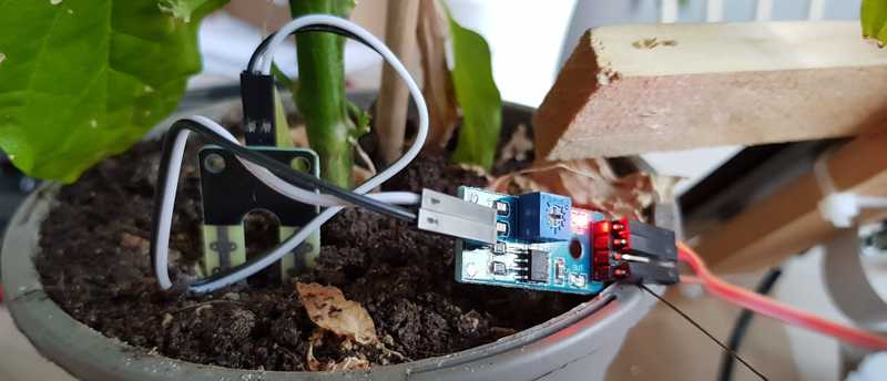
In order to ensure that each plant gets the right amount of water, we need to measure the moisture contents of the soil quite accurately. The easiest way to do that is to measure the voltage between two electrodes in the soil.
This is part 3 of this series; here is part 1, part 2, part 4, part 5.
To do that, I’m using a few different parts (mostly off-the-shelf stuff):
- Two electrodes to put into the soil.
- An amplifier circuit to amplify the measured voltage between the electrodes.
- An Analog-to-Digital Converter (ADC) to measure the voltage and convert it into a signal we can process.
Wiring up an ADC
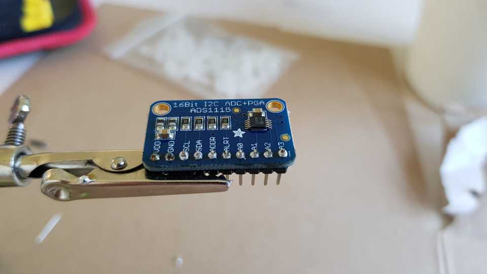
The ADC I’m using is a Texas Instruments ADS1115. It’s an ADC that has its own built-in gain stepper and support for four different analog channels, and interfaces with a device over I2C which is an easy-to-use communications bus for embedded devices.
Adafruit has built a ready-made PCB for using this chip. This is probably one of my worst soldering jobs ever, by the way:
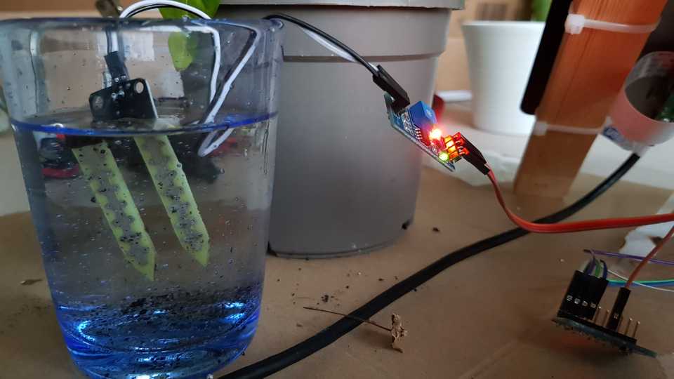
Now we can wire up the ADC to the Raspberry Pi using one 3.3V pin, one ground, and two pins for the I2C bus. Then, we can wire up the moisture sensor to another 3.3V pin and ground, and connect the analog output signal of the moisture sensor to the A0 channel of the ADC.
It looks like a mess, but it works:
Creating an ADC driver
Now we need to create a driver to control the ADC. I chose to implement one in Rust; if you want to see the finished result, documentation is available for the library I created.
The process is quite simple. We create a new Rust library with some dependencies:
# Create a new Rust Cargo project
$ cargo init --lib ads1x15
     Created library project
$ cd ads1x15
# Add some dependencies
$ cargo add i2cdev bitflags failure byteorder
According to the data sheet for the chip, to read
voltages we need to send a command to a Config register over I2C to do a voltage conversion, wait
a little bit for the conversion to complete, and read back the result from a Convert register.
What this effectively means is that we need to send 3 bytes to the device:
0x01to select theConfigregister.-
The 16 bits
0b1_100_000_1_100_0_0_0_11(grouped with underscores for ease of reading):1means start a single measurement/conversion.100means use inputA0where we hooked up the moisture sensor.000means configure the PGA for measuring a range of +/-6.144V.1means run in a power-down single-shot mode.100means gather 1600 samples per second.- The next 3 bits are for various flags that we won’t use.
11means disable comparator mode and don’t use interrupts; we will poll for the result.
Then, we wait for a few milliseconds. After that, we write one byte 0x00 to select the
Convert register, and read two bytes to get the sensor value. What’s a bit funny is that we need
to set the Config register in little-endian order, but read the Convert register in big-endian
order.
Let’s start modeling this in Rust. We create a struct to represent the device:
/// An interface to an ADS1x15 device that can be used to control the device over I2C.
#[derive(Debug)]
pub struct Ads1x15<D> {
    device: D,
    gain: Gain,
    model: Model,
}
The D is some abstract interface to the I2C bus. Let’s define Gain and Model (there are some
variations of ADS1x15 chips):
/// Configuration for the gain setting of the device.
#[derive(Clone, Copy, Debug)]
#[allow(non_camel_case_types)]
pub enum Gain {
    /// The measurable range is ±6.144V.
    Within6_144V,
    /// The measurable range is ±4.096V.
    Within4_096V,
    /// The measurable range is ±2.048V.
    Within2_048V,
    /// The measurable range is ±1.024V.
    Within1_024V,
    /// The measurable range is ±0.512V.
    Within0_512V,
    /// The measurable range is ±0.256V.
    Within0_256V,
}

#[derive(Debug)]
enum Model {
    ADS1015,
    ADS1115,
}
Now we can write the code for reading values from the device. I also added a type called Channel
that can be used to support channels other than A0 but for this example, we can assume that
self.gain.as_reg_config() sets the 000 gain bits and channel.as_reg_config_mux_single()
simply sets the 100 bits mentioned above:
impl<D> Ads1x15<D>
where
    D: i2cdev::core::I2CDevice,
{
    fn read_single_ended(&mut self, channel: Channel) -> Result<f32, D::Error> {
        use byteorder::ByteOrder;

        // Set some default bits in the Config register
        let mut config = reg::RegConfig::default();
        // Configure our desired gain setting
        config.insert(self.gain.as_reg_config());
        // Configure our channel to measure (e.g. A0)
        config.insert(channel.as_reg_config_mux_single());

        // Set 'start single-conversion' bit
        config.insert(reg::RegConfig::OsSingle);

        // Write to the Config register over I2C
        let mut write_buf = [reg::Register::Config.bits(), 0u8, 0u8];
        byteorder::LittleEndian::write_u16(&mut write_buf[1..], config.bits());
        self.device.write(&write_buf)?;

        // Wait a bit according to the chip's specifications
        thread::sleep(self.model.conversion_delay());

        // Read back sensor data
        let mut read_buf = [0u8, 0u8];
        self.device.smbus_write_byte(reg::Register::Convert.bits())?;
        self.device.read(&mut read_buf)?;

        // Convert the sensor data to volts according to chip's specifications
        let value = self.model
            .convert_raw_voltage(self.gain, byteorder::BigEndian::read_i16(&read_buf));

        Ok(value)
    }
}
Now we need to quickly look at the data sheets again to implement model.conversion_delay() and
model.convert_raw_voltage(). We find out that the conversion takes about 8 milliseconds for the
ADS1115 chip, as well as the conversion factors for the various gains settings:
impl Model {
    fn conversion_delay(&self) -> time::Duration {
        match *self {
            Model::ADS1015 => time::Duration::from_millis(1),
            Model::ADS1115 => time::Duration::from_millis(8),
        }
    }

    fn convert_raw_voltage(&self, gain: Gain, value: i16) -> f32 {
        match *self {
            Model::ADS1015 => {
                let value = (value >> 4) as f32;
                match gain {
                    Gain::Within6_144V => value * 3.0000e-3,
                    Gain::Within4_096V => value * 2.0000e-3,
                    Gain::Within2_048V => value * 1.0000e-3,
                    Gain::Within1_024V => value * 5.0000e-4,
                    Gain::Within0_512V => value * 2.5000e-4,
                    Gain::Within0_256V => value * 1.2500e-4,
                }
            }
            Model::ADS1115 => {
                let value = value as f32;
                match gain {
                    Gain::Within6_144V => value * 1.8750e-4,
                    Gain::Within4_096V => value * 1.2500e-4,
                    Gain::Within2_048V => value * 6.2500e-5,
                    Gain::Within1_024V => value * 3.1250e-5,
                    Gain::Within0_512V => value * 1.5625e-5,
                    Gain::Within0_256V => value * 7.8125e-6,
                }
            }
        }
    }
}
And that’s it! There is of course a bunch of more code in the library as well, feel free to have a look: https://github.com/dflemstr/ads1x15
Measuring the moisture level
Now we can create a simple test program to try out our driver and moisture sensor!
extern crate i2cdev;
extern crate ads1x15;
extern crate failure;

use std::thread;
use std::time;

fn main() -> Result<(), failure::Error> {
    // Connect to the i2c bus of the Raspberry Pi:
    let dev = i2cdev::linux::LinuxI2CDevice::new("/dev/i2c-1", 0x48)?;
    // Use our driver that we made above to control the chip:
    let mut dac = ads1x15::Ads1x15::new_ads1115(dev);

    // Loop forever
    loop {
        // Read the voltage of the A0 channel
        let value = dac.read_single_ended(ads1x15::Channel::A0)?;
        eprintln!("A0 = {}V", value);

        thread::sleep(time::Duration::from_secs(1));
    }
}
If we run this program, it outputs some data!
$ cargo build
$ sudo target/debug/examples/test
A0 = 2.216625V
A0 = 2.2198126V
A0 = 2.2211251V
...
If we put the sensor into a glass of water, the data changes!
...
A0 = 0.4494375V
A0 = 0.4505625V
A0 = 0.46068752V
A0 = 0.4640625V
A0 = 0.47343752V
...
This proved to work brilliantly! Now we’re ready to use the sensor data for something useful!


